Getting Started
This document will help new users get started using the support tool to interact with an EVB running VelocityDRIVE-SP.
| The tools covered in this section are command-line tools, running in a Linux environment (can run under Windows if using WSL or VirtualBox). Microchip also offers a Windows GUI tool which can be used to interact with switches running VelocityDRIVE-SP. Many users may find it easier to get started using the GUI tools. To get access to this tool, contact your sales or support representatives from Microchip and ask for VelocityDRIVE-CT. |
| Users who decide to use VelocityDRIVE-CT instead of the command-line tools described here can still benefit from reading the configuration guides. |
The basic setup should look like this:

As a prerequisite to this document, the following is needed:
-
A supported evaluation board with VelocityDRIVE-SP
-
Check the list of VelocityDRIVE-SP supported EVBs here
-
-
A PC capable of providing a Linux environment
-
Either a native Linux PC, VirtualBox hosting a Linux installation, or WSL
-
Certain tools need to be installed which will require root access
-
Access to serial ports (UART/tty) from the Linux environment
-
1. Booting
To get started with a new evaluation board, it is a good idea to start by confirming the basic UART connectivity. To do this, add power to the board and connect the USB console to the host PC, and open the UART using a terminal emulation program like minicom, picocom, putty, or teraterm.
The UART/serial settings must be configured as follows:
flowcontrol    : none
baudrate       : 115200
parity         : none
databits       : 8
stopbits       : 1
Here we will use picocom to connect to /dev/ttyACM0:
$ picocom -b 115200 /dev/ttyACM0The VelocityDRIVE-SP firmware will only print an announce frame once at boot, and after this, it will remain silent until a request is received or a trace message is issued. To see if VelocityDRIVE-SP is loaded on the board and capable of running, it is easiest to hit the reset button while your terminal emulation application of choice is still running.
Doing so should result in the following message being seen in the console:
>AVelocitySP-v2024.12 0 300 2
                             <<dfd3
This looks strange at first, but this is expected. The console is not used to implement a traditional human-friendly CLI, but rather a machine interface called MUP1, which facilitates client software to communicate with the device. Go to the mup1 technology document if the full set of details is of interest.
For casual users, it is enough to understand that all MUP1 frames start with a
> marker. The character following the start-of-frame marker is a type field,
and here A means announcement. The end-of-frame marker is marked by a < then
an optional padding byte and then a 4-digit checksum.
The text seen between the start/end of frame markers is the firmware version along with MUP1 settings.
It is also possible to manually issue a MUP1-Ping which can be used to determine if the DUT is still there.
To do this, paste in the >p<<8553 message in the console, and watch out for
the ping response which should look like this:
>PVelocitySP-v2024.12 80553 300 2<ab69
Beyond this, it is practically impossible to use the MUP1 interface along with a
classical terminal emulator. The following part of the getting started guide
will provide the instructions to get started with the tools called mup1cc and
mup1ct which are client applications supporting MUP1.
| Remember to quit the terminal application before moving on, as only one application can use the UART at a time in Linux. |
If things are working, skip the troubleshooting section to proceed with this guide.
1.1. Troubleshooting
If the announce message and/or the ping-response is not seen on the console, then it is a good idea to troubleshoot this before moving on. Here is a bit of guidance:
1.1.1. ttyACM0 is not there and/or is silent
Several things can result in this behavior. But to debug this, it is useful to have a basic understanding of how most of the evaluation boards are designed with regards to the USB console interface. This is illustrated here:

As shown in the figure, the USB-2-UART converter is a separate component on the board. This means that the USB device will not appear if the cable is not properly connected.
It is also worth noticing that the USB-to-UART converter is powered by USB. On some (smaller) boards, USB is powering the entire board, and others need an external power supply. But the UART-LED(s) can show activity even if the board requires external power. This is because the USB-2-UART converter is a USB powered device, and the switch-core may not be that.
With this information, let’s check a few things that can go wrong.
1.1.1.1. Power Issues
The USB cable must be connected to a PC and the board, and the LED with the power-label on the EVB must be on.
If this is not the case, check if the board needs external power in addition to the USB power driving the UART converter.
1.1.1.2. Unexpected Console Activity
Most of the evaluation boards support specific software packages, and it could be that the board has been prepared with a different software package. In this case, the board may be booting into UBoot instead of VelocityDRIVE-SP.
The first thing to check is the boot media controlled by a DIP switch. The DIP
switch must be configured to boot from NOR. Both the LAN966x and LAN969x
families of chips must have the DIP switches controlling power set as follows to
boot from NOR:
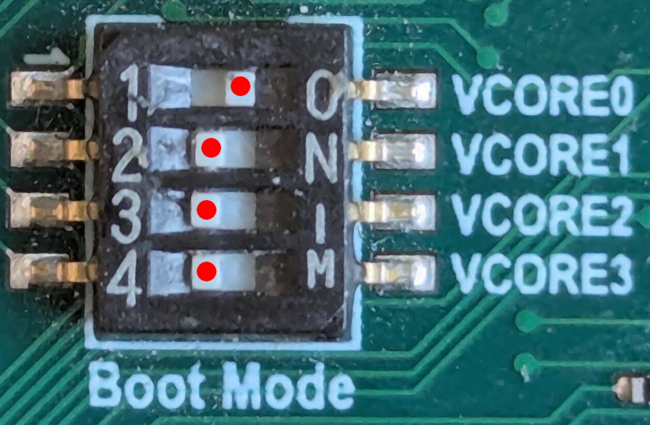
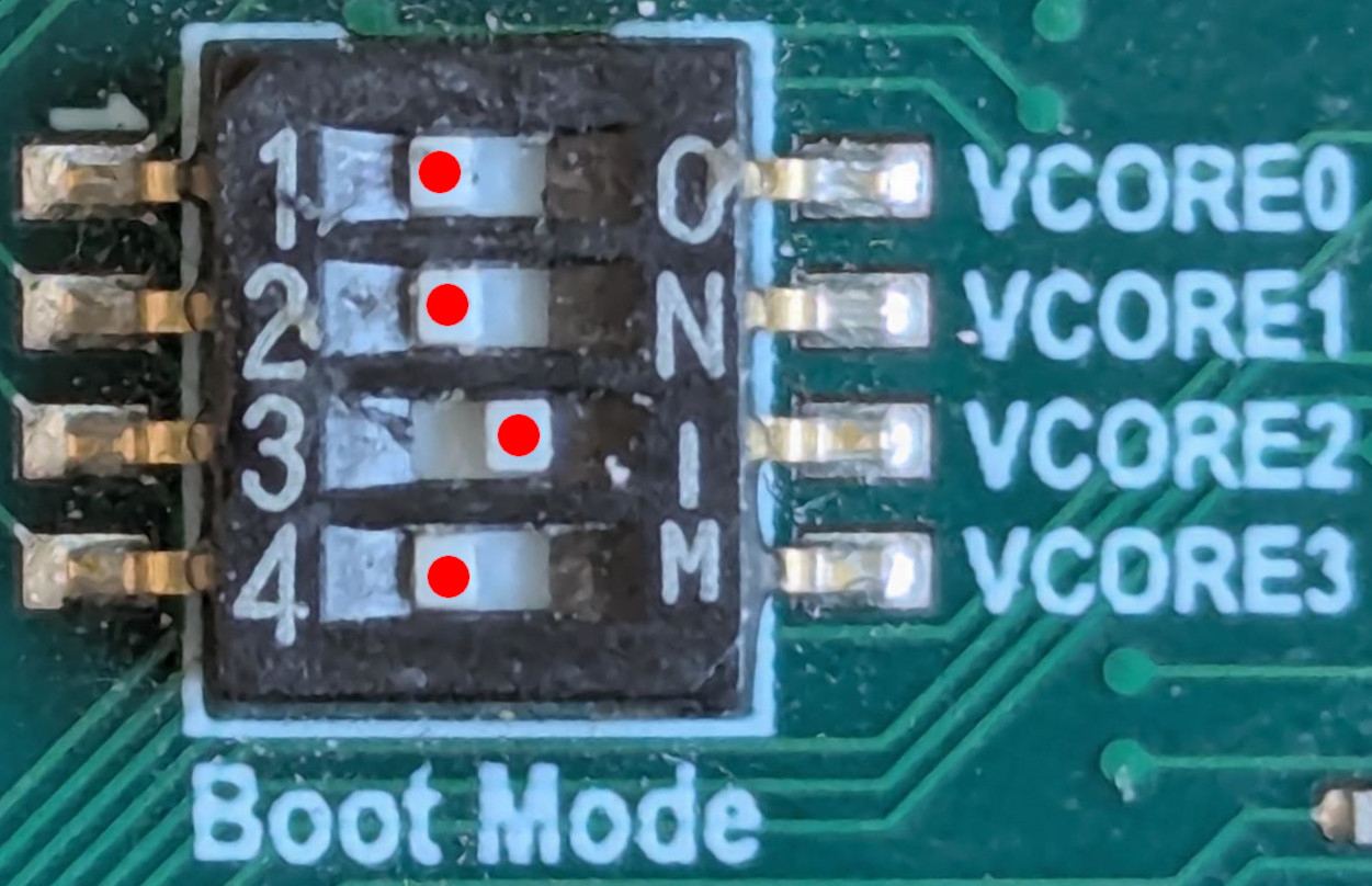
         NOR With Bootloader Trace  | NOR Without Bootloader Trace
------------------------------------+-----------------------------
VCORE0:                         ON  |                          OFF
VCORE1:                        OFF  |                          OFF
VCORE2:                        OFF  |                           ON
VCORE3:                        OFF  |                          OFF
It is recommended to start with traces, and once things are working, change to the setting without the bootloader traces.
The following image shows how to set the DIP switches to boot from NOR with traces:
The following image shows how to set the DIP switches to boot from NOR without traces:
After changing the DIP switches, reset the board and see if it helps.
If strapping was set correctly and/or if the board is still not booting (fatal error from the bootrom) or booting into UBoot, then it is necessary to follow the de-brick procedure described in the EVB section. The LAN969x de-brick procedure can be found here. To follow this procedure, one will need to have a firmware image to program on the board. If you do not have this, reach out to your Microchip contact to get that.
1.1.1.3. Device Naming
The USB serial device may be called something else. Different Linux
distributions use different naming conventions for the devices, and if multiple
serial devices are connected, then a sequence number is typically incremented
(e.g., it may be called ttyACM1).
To check what it is called, it is easiest to check the kernel log (requires root access) while connecting the device. Here is the procedure to follow:
-
Disconnect the device
-
Run the
sudo dmesg -wcommand as shown below -
Wait for output to settle
-
Connect the device, and see what events are generated
$ sudo dmesg -w
[2355481.783627] usb 1-10: new full-speed USB device number 102 using xhci_hcd
[2355481.930538] usb 1-10: New USB device found, idVendor=04d8, idProduct=00dd, bcdDevice= 1.00
[2355481.930546] usb 1-10: New USB device strings: Mfr=1, Product=2, SerialNumber=0
[2355481.930549] usb 1-10: Product: MCP2221 USB-I2C/UART Combo
[2355481.930551] usb 1-10: Manufacturer: Microchip Technology Inc.
[2355481.934864] cdc_acm 1-10:1.0: ttyACM0: USB ACM device
[2355481.936096] mcp2221 0003:04D8:00DD.0053: USB HID v1.11 Device [Microchip Technology Inc. MCP2221 USB-I2C/UART Combo] on usb-0000:00:14.0-10/input2
In the kernel log message above, we can see the ttyACM0 meaning that the newly
connected board can be accessed at /dev/ttyACM0.
Alternatively, it is also possible to check changes in the content of the /dev
folder:
$ # Disconnect the device
$ ls /dev > /tmp/before
$ # Connect the device
$ ls /dev > /tmp/after
$ diff /tmp/before /tmp/after # to see what changed
20a21
> gpiochip1
37a39
> i2c-3
151a154
> ttyACM0
If no devices can be identified using these methods, then check the cables, and/or if the Linux machine being used has the needed drivers.
Some distributions install all kernel drivers as modules. If the system
has been updated, and a new kernel has been installed, and the system has not
been rebooted, then it is likely the modules belonging to the running kernel have
been deleted, and cannot be loaded. In this case, some dmesg messages are seen,
but no device is attached. To fix this, remember to reboot the system after kernel
updates.
|
All the following examples will use /dev/ttyACM0. Make sure to use the
correct name on your system.
1.1.2. Permission-Related Error Message
When opening the terminal emulation application, a permission-related error is printed.
In this case, check the permission of the serial port device and the credentials of your current user:
$ ls -la /dev/ttyACM0  # check serial port permissions
crw-rw---- 1 root uucp 166, 0 Jan 29 14:10 /dev/ttyACM0
$ id # check credentials of current user
uid=1000(user) gid=1000(user) groups=1000(user),5(tty),100(users),971(docker),986(uucp)
Here the serial port is owned by the root user, and the uucp group. Access
should work as the current user is a member of the uucp group.
If permissions are not set up correctly, the easiest solution is often to give everybody access:
$ sudo chmod a+rw /dev/ttyACM0
$ ls -la /dev/ttyACM0
crw-rw-rw- 1 root uucp 166, 0 Jan 29 14:10 /dev/ttyACM0
After this, all users with access to the system have access to the UART.
2. Prepare the PC Environment
The majority of this guide will use tools from the velocitydrivesp-support repository. Let’s start by cloning this repository:
$ git clone https://github.com/microchip-ung/velocitydrivesp-support
$ cd velocitydrivesp-support
The easiest and recommended way to use the tools just cloned is to run them
through a small script called dr which will simply start a docker container,
run the requested command, and then stop the docker container again.
If for some reason it is not desired to use dr and docker, then it is
still possible to use the scripts in this repository. But the majority of the
scripts are written in Ruby and have various dependencies. To prepare a PC to
run these examples without docker, then use the dockerfile
here
to see the list of packages installed.
|
To install dr, run the following command (to learn more about dr, check the
readme file here).
$ sudo curl -o /usr/local/bin/dr https://raw.githubusercontent.com/microchip-ung/docker-run/refs/heads/main/dr
$ sudo chmod +x /usr/local/bin/dr
The next step is to confirm that docker is installed, running, and working.
2.1. Docker Installation
$ docker imagesThis should print a (possibly empty) list of images. If it does so, skip the rest of this session. If you see any kind of error, then continue.
The following steps will show how to install docker on a Fedora 40 workstation:
# On Fedora 41
$ sudo dnf install docker-cli docker-ce containerd
# On Fedora 40
$ sudo dnf install moby-engine containerd
Docker needs a backend service running, let’s start that:
$ sudo systemctl enable --now dockerAdd the current user to the docker group:
$ sudo usermod -aG docker $USERLogout and login again to have the list of groups updated (or run newgrp
docker to join the group in the current session without logging out and in again).
Now let’s repeat the command to list images and see if it works:
$ docker imagesIf this is still not successful, then please seek help to get docker working properly before continuing.
2.2. First Use of dr
Now that docker is installed and working, we are ready to use dr for the
first time. The dr script will look for a file called .docker.env and if the
configured docker image is not downloaded, it will start by downloading it. Let’s
invoke a simple command to check this:
$ dr lsIf running for the first time, then you will see some docker output downloading
the image. Depending on network speed, this will take from a few minutes to hours
to complete. Once the download has completed, then the ls command will run and
the content of the folder should be listed.
When using the dr command after this, the docker image will be cached, and
it should only take a second or two to bring up the docker image where the
command is invoked.
It is possible to run dr bash to open a long-lived interactive bash
shell within the docker image. This can be faster if using a small PC where it
takes a long time to spin up an image, or if using a std-in/out/err
redirection which can also be confusing when using the dr command.
|
3. Basic Management Using CORECONF over MUP1
With docker fully configured, and a board confirmed to run VelocityDRIVE-SP, we are ready to do some basic management of the board.
This section will present some copy-paste’able commands/examples which we
encourage new users to try out. All the examples here will be using the mup1cc
tool which is part of the docker image.
| Most of the examples in this section will start by preparing a request message which is written to a file, and then use this file in the following command. To do this, we use the here document syntax and pipe the content into a file. This is just a convenient way to make the commands copy-paste’able, but at the end of the day, it does not matter how the content in the file is written - as long as it is written correctly. |
Let’s start by confirming that the script can run, by invoking the script with the help option (output has been truncated):
$ dr mup1cc --help
Usage: /home/m31684/work/sw-lmstax4/support/scripts/mup1cc [options]
    -h, --help                       The MUP1CC help
...
The mup1cc tool can be used to access the CORECONF resources over MUP1, and
when doing so, it will convert between the CBOR encoding which is what it does on
the wire, and a variant of RFC7951 encoding which is used as input and output
for this tool. For a more in-depth description of CORECONF, CBOR, and RFC7951,
please reference the documents in the technology section.
| This tool only works if no other process has opened the serial device. Make sure to close any open terminal emulators. |
As a first step, let’s get the running configuration along with the status and
counters of the entire switch. To do this, the serial device must be specified
using the -d flag, and the CoAP method must be set to get using the -m
flag:
$ dr mup1cc -d /dev/ttyACM0 -m get
Opening serial port at /dev/ttyACM0
---
ietf-interfaces:interfaces:
  interface:
  - name: '1'
    type: iana-if-type:ethernetCsmacd
    enabled: true
    oper-status: down
    if-index: 1
    phys-address: 22-94-0D-28-97-01
    statistics:
      in-octets: '0'
      in-unicast-pkts: '0'
      in-broadcast-pkts: '0'
...
Let’s try to get the interface status of port 1 and 2:
$ cat <<-EOF > fetch-req-port-get.yaml
- "/ietf-interfaces:interfaces/interface[name='1']"
- "/ietf-interfaces:interfaces/interface[name='2']"
EOF
$ dr mup1cc -d /dev/ttyACM0 -m fetch -i fetch-req-port-get.yaml
Try running the command to see the actual output.
3.1. IP Address Configuration
As an alternative to the designated point-to-point UART/serial-based communication, it is also possible to do in-band management using an IPv4 network. To do this, we need to create an L3 interface and assign an IP address.
| For a full explanation of how the IP configuration ties into the VLAN configuration, see the document on IP based management. |
The RFC7951 encoded CORECONF ipatch request below will create a new L3 interface
called L3V1, and it will assign the ip and prefix-length attributes to
"10.0.0.1" and 24 respectively:
$ cat <<-EOF > ipatch-req-set-ip.yaml
- ? "/ietf-interfaces:interfaces/interface"
  : name: "L3V1"
    type: iana-if-type:l3ipvlan
    ietf-ip:ipv4:
      address:
      - ip: "10.0.0.1"
        prefix-length: 24
EOF
$ dr mup1cc -d /dev/ttyACM0 -m ipatch -i ipatch-req-set-ip.yaml
Once this is done, it would be possible to do a simple ping test (remember to connect and configure the host PC accordingly).
3.2. Disable DTLS
The firmware is designed to be secure by default, which is a great help to do secure installations, but if the setup is being used for development, it can be desirable to start without the security layer enabled.
| As of VelocityDRIVE-CT-2024.12 release, DTLS is not supported in the Windows tool. It is a roadmap item which we are working on, but for now, it is also required to disable DTLS if using VelocityDRIVE-CT to manage the DUT over an IPv4 network. |
Setting security mode to no-sec also disables authentication
entirely. This configuration should only be used in an environment which is
secured by other means, or where security and authentication are not needed.
|
The request below simply sets the security mode to no-sec which means that DTLS
is disabled.
$ cat <<-EOF > ipatch-req-no-sec.yaml
- "/mchp-velocitysp-system:coap-server/config/security-mode": "no-sec"
EOF
$ dr mup1cc -d /dev/ttyACM0 -m ipatch -i ipatch-req-no-sec.yaml
Once the request is completed, the configuration must be saved in startup-config, and the device needs to be reset to apply the new security configuration. This is the only configuration change which requires a reboot; all other configurations are applied directly.
To save the configuration, an RPC needs to be triggered as shown below:
$ cat <<-EOF > rpc-req-save-running.yaml
- "/mchp-velocitysp-system:save-config":
EOF
$ dr mup1cc -d /dev/ttyACM0 -m post -i rpc-req-save-running.yaml
We can now finally reboot the device and connect to it over IP without DTLS:
$ cat <<-EOF > rpc-req-restart.yaml
- "/ietf-system:system-restart":
EOF
$ dr mup1cc -d /dev/ttyACM0 -m post -i rpc-req-restart.yaml