LAN966x / LAN969x PCIe Endpoint with Raspberry PI 4 CM as external CPU
This describes how to use the combination of a Raspberry PI 4 Compute Module with the Raspberry PI Compute Module IO Board and a Microchip PCIe endpoint board.
The following endpoint boards are supported. All three use a Raspberry PI 4 Compute Module as the host CPU; the first two mount it on the Raspberry PI Compute Module IO Board.
| Host board | Board | SoC | Ports exposed to the host |
|---|---|---|---|
LAN9662 (LAN966x) |
4 |
||
LAN9696 (LAN969x) |
29 |
||
LAN966x |
4 |
The EVB-LAN9662-NIC and EVB-LAN9696-24port boards are pre-configured for PCIe boot mode.
Both the Buildroot BSP and the Yocto BSP build an image for this setup. The two build systems use the same U-Boot environment layout, so the boot procedure is the same. Only the artifact names differ. See Using the Buildroot image and Using the Yocto image.
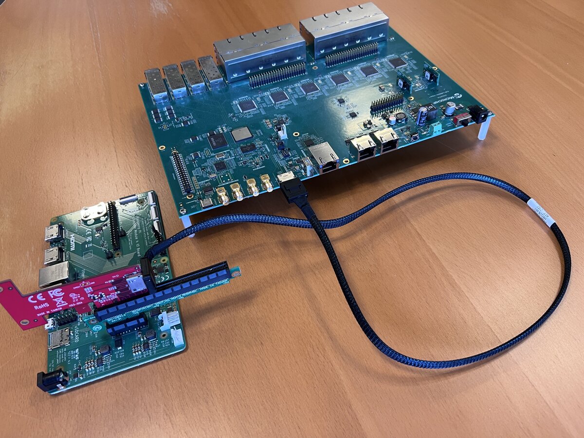
EVB-LAN9696-24port cabling
The EVB-LAN9696-24port does not plug directly into the IO Board’s PCIe slot. Instead, a PCIe-to-Oculink adapter is fitted to the IO Board, and an Oculink cable runs from there to the Oculink connector on the LAN969x EVB.
Resources
This configuration uses the Raspberry PI 4 as the host CPU and therefor the device tree used for this setup is the one for the Raspberry PI, so you will need to consult the Raspberry PI documentation for details about this SoC.
Kernel Configuration
The configuration used is a very slim version of the standard Raspberry PI 4 configuration. Only the bare minimum needed for a network setup has been added, so you will not be able to use e.g. display, mouse and keyboard combo with this configuration. Instead you will have to use a serial/USB console to a workstation to monitor and interact with the system.
Devicetree Configuration
The system uses the Raspberry PI 4’s device tree with a addition of a PCIe device node that hosts all the device tree nodes for the PCIe endpoint boards onboard devices.
These childnodes are mapped into the PCIe Controllers Bus Window to allow the PCIe SwitchDev driver to access all the needed hardware registers via the PCIe Bus.
One FIT image holds a device tree for each supported endpoint board, and each device tree has its own FIT configuration:
| FIT configuration | Device tree | Board |
|---|---|---|
|
|
EVB-LAN9662-NIC |
|
|
EVB-LAN9696-24port |
|
|
PCB8309 |
rpi is the default configuration of the FIT image.
U-Boot Environment
The boot partition holds a uboot.env file. A valid stored environment replaces the environment compiled into U-Boot,
so nothing is inherited from the standard rpi.env.
These are the variables that select what is booted:
| Variable | Description |
|---|---|
|
FIT configuration to boot: |
|
Address where the FIT image is loaded ( |
|
File name fetched by |
|
Boots the bare FIT from the boot partition, root file system on |
|
Boots |
rootargs_mmc and rootargs_ram set the root file system arguments, and setup builds the final bootargs from
console, rootargs and bootargs_extra.
loadaddr must stay above 0x0e000000, which is where bootm copies the device tree out of the FIT image.
|
Selecting the endpoint board
Set the pcb variable in the U-Boot environment to match the board you have mounted, then save the environment:
EVB-LAN9662-NIC:
setenv pcb rpi
saveenv
EVB-LAN9696-24port:
setenv pcb rpi-lan969x
saveenv
PCB8309:
setenv pcb pcb8309
saveenv
Resetting the endpoint board
For the EVB-LAN9696-24port you need to reset the board with its reset button just before U-Boot boots the kernel on the RPi4 CM.
The RPi4 cannot reset the LAN969x SoC without also resetting the PCIe link, so the reset has to happen before the PCIe connection is initialized.
Using the Buildroot image
The BSP release file mchp-brsdk-arm64-<version>.tar.gz contains the image file rpi4cm.img that is needed to boot the
system and get the PCIe endpoint enabled.
When unpacking the release file mentioned above you will find the image file here:
mchp-brsdk-arm64-<version>/arm64-armv8_a-linux-gnu/standalone_rpi/release/rpi4cm.imgYou will also find a readme file that explains the image content and the boot process:
mchp-brsdk-arm64-<version>/arm64-armv8_a-linux-gnu/standalone_rpi/release/README.adocWrite rpi4cm.img to the CM4 eMMC or to an SDCard as described in Writing the Raspberry PI 4 CM eMMC
and Writing the Raspberry PI 4 CM SDCard. This file is the <image-file> used by the dd commands
there.
Buildroot boot artifacts
The boot partition holds two FIT images:
| File | Content |
|---|---|
|
Kernel and device trees. The root file system is on |
|
Kernel, device trees and a SquashFS root file system. |
The Buildroot environment has an extra variable for the second image:
| Variable | Description |
|---|---|
|
Boots |
To boot the RAM root file system:
run bootcmd_ramTo boot a single configuration by hand:
run rootargs_mmc ; run setup ; load mmc 0:1 ${loadaddr} fit.itb ; bootm ${loadaddr}#rpi-lan969xThe environment is generated from overlays/board/raspberrypi/uboot.env.txt by mkenvimage in post-image.sh.
Using the Yocto image
The Yocto BSP builds this setup with the rpi4cm machine. Build the bootable disk image with:
MACHINE=rpi4cm bitbake mchp-standalone-gpt-imageThe artifacts are placed in build/tmp-mchp/deploy/images/rpi4cm:
| Artifact | Content |
|---|---|
|
Bootable disk image with a FAT32 boot partition and an ext4 root partition |
|
Bare FIT with kernel and device trees, placed in the boot partition as |
|
FIT with kernel, device trees and the SquashFS root file system |
|
U-Boot binary |
|
U-Boot environment |
Write mchp-standalone-gpt-image-rpi4cm.rootfs.gpt to the CM4 eMMC or to an SDCard as described in
Writing the Raspberry PI 4 CM eMMC and Writing the Raspberry PI 4 CM SDCard. This
file is the <image-file> used by the dd commands there.
Yocto network boot
The Yocto boot partition holds only the bare FIT, so use bootcmd_network to boot the FIT that embeds the root file
system. Serve fitImage-mchp-standalone-image-rpi4cm.bin from your TFTP server and point bootimage at it:
setenv bootimage fitImage-mchp-standalone-image-rpi4cm.bin
saveenv
run bootcmd_network
The environment is generated from meta-mchp-ncs/recipes-bsp/u-boot/files/rpi4cm.txt by mkenvimage in
u-boot-mchp_2021.04.bb.
For general Yocto build instructions see Building Yocto BSP from Source.
Disk image file name
The two build systems name the bootable disk image differently:
| Build system | Disk image file |
|---|---|
Buildroot |
|
Yocto |
|
The dd commands in the next two sections write <image-file>. Substitute the name from this table.
Writing the Raspberry PI 4 CM eMMC
First mount the CM4 module on the IO board and put a strap on the J2 pinheaders first position to disable eMMC boot.
Clone the RPI usbboot repo and build the tool:
git clone --depth=1 https://github.com/raspberrypi/usbboot
cd usbboot
make
Attach the RPI4 IO board (with the mounted CM) via a nanoUSB cable (to the USB slave port on the IO Board) and start the USB driver:
sudo ./rpibootFind the new usb device (e.g. /dev/sdX) using lsblk
lsblk --output NAME,FSTYPE,LABEL,UUID,PARTUUID,MOUNTPOINTWrite the image to the USB device:
sudo dd if=<image-file> of=/dev/sdX bs=8M status=progress oflag=directWhen done you should have two partitions on the device: a FAT32 boot partition labelled BOOT, and an unlabelled ext4
root file system.
lsblk --output NAME,FSTYPE,LABEL,SIZE,UUID,PARTUUID

NAME   FSTYPE LABEL  SIZE UUID                                 PARTUUID
sda                 29.1G
├─sda1 vfat   BOOT   256M 4D9B-9EF0                            4429b092-01
└─sda2 ext4          764M bed286d6-ae1a-4264-92c6-6d52941c1520 4429b092-02
Mount the boot device in ~/mnt/boot and edit the config.txt file and create an empty ssh file (to enable the ssh server):
mkdir -p ~/mnt/boot
sudo mount /dev/sdX1 ~/mnt/boot/
sudo touch ~/mnt/boot/ssh
sudo nvim  ~/mnt/boot/config.txt
In the config.txt file you should add an overlay to enable the USB ports (not the slave USB port) and a uart setting to enable the serial console via the PIN header, and enable uart support for the second stage bootloader (to get the logging out):
dtoverlay=dwc2,dr_mode=host
enable_uart=1
uart_2ndstage=1
Serial Console
To use the serial console to the Linux Kernel running on the Raspberry Pi you can attach a serial/USB converted to the J8 connector on the RPI 4 IO Board.
| Pin | Function |
|---|---|
J8-6 |
Ground |
J8-8 |
RPI TX |
J8-10 |
RPI RX |
You should then be able to get to the Linux console and login as root (no password).
Normal Boot
Remove the strap on the pinheader and powercycle the Raspberry PI board to start the system.
Using the serial console you should be able to login as root and see that you now have a number of available network interfaces: 1 on the Raspberry PI IO Board and 4 or 29 depending on the endpoint board.
Writing the Raspberry PI 4 CM SDCard
Insert the SDCard into a card reader slot and locate the new device using e.g. dmesg or lsblk and then write the
image to the new device using dd:
sudo dd if=<image-file> of=/dev/sdX bs=8M status=progress oflag=directWhen done you should have two partitions on the device: a FAT32 boot partition labelled BOOT, and an unlabelled ext4
root file system.
lsblk --output NAME,FSTYPE,LABEL,SIZE,UUID,PARTUUID

NAME   FSTYPE LABEL  SIZE UUID                                 PARTUUID
sda                 29.1G
├─sda1 vfat   BOOT   256M 4D9B-9EF0                            4429b092-01
└─sda2 ext4          764M bed286d6-ae1a-4264-92c6-6d52941c1520 4429b092-02
You can now boot the system. You may want to use a serial/USB console as described in the previous section.