Sparx5
1. Sparx5 Family Overview
The Sparx5 family consists of the following SKUs:
| Port Mapping | VSC7546 | VSC7549 | VSC7552 | VSC7556 | VSC7558 |
|---|---|---|---|---|---|
Maximum bandwidth [Gbps] |
64 |
90 |
128 |
160 |
200 |
Maximum number of ports |
64 |
64 |
64 |
64 |
64 |
Max number of 1G ports |
64 |
64 |
64 |
64 |
64 |
Max number of 1G SGMII ports |
32 |
32 |
32 |
32 |
32 |
Max number of 100FX ports |
24 (Note 1) |
24 |
24 |
24 |
24 |
Max number of 2.5G ports |
24 |
36 |
48 |
64 |
64 |
Max number of 5G ports |
12 |
18 |
24 |
32 |
32 |
Max number of 10G ports |
6 |
9 |
12 |
16 |
20 |
Max number of 25G ports |
0 (Note 2) |
0 (Note 2) |
4 |
6 |
8 |
NPI port (5G) |
1 |
1 |
1 |
1 |
1 |
|
2. Evaluation Board Overview
This chapter describes the different Sparx5 Evaluation Boards.
There are currently two Sparx5 evaluation boards available:
-
VSC5640EV - Providing 20 SPF+ ports with 10Gbps speed.
-
VSC5641EV - Providing 64 1Gbps Ethernet PHY ports and 4 25Gbps SFP+ ports
The two boards can be mounted with either SPI NAND or eMMC enabled (but not both).
2.1. VSC5640EV Sparx5 20xSFP Evaluation board
The VSC5640EV evaluation board provides 20 SFP ports that can be used for high speed network connectivity.
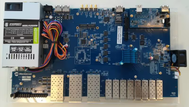
The board features:
-
1x VSC7558 Switch (with Enterprise Ethernet features).
-
12x SFP+ front 10G module slots (connected to VSC7558 through SFI).
-
8x SFP28 front 25G module slots (connected to VSC7558 through SFI high speed).
-
Optional, one additional 10/100/1000BASE-T (RJ45) Ethernet port (on-board VSC8211 PHY connected to VSC7558 through SGMII).
-
On board Sync-E DPLL Redwood/ZL30772 (replaceable with the cheaper non-PTP ZL30256) to generate the 3 required clocks … and support for a range of Microchip Sync-E modules through the Sync-E feature connector – note, that all clocks still goes through ZL30772.
-
Four SMAs connectors and two ITU-T G.8275 compliant RS422 interfaces (1 PPS
ToD input and output) for Sync-E and PTP applications. -
Serial UART port for local management and software debugging by using a firmware driven Command Line Interface (CLI).
-
Reset button with one-shot reset (that is, so button state can be read by firmware after board reset, e.g. for a “reset to factory defaults” function).
-
System status LED (tri-color green/orange/red).
-
Port status LED (bi-color green/yellow) per network port for link and activity indication.
-
Standard 240/110VAC 200W PSU.
2.2. VSC5641EV Sparx5 48xCu Evaluation board
The VSC5641EV evaluation board provides 48 1G Copper PHY interfaces and 4 high speed SFP ports.
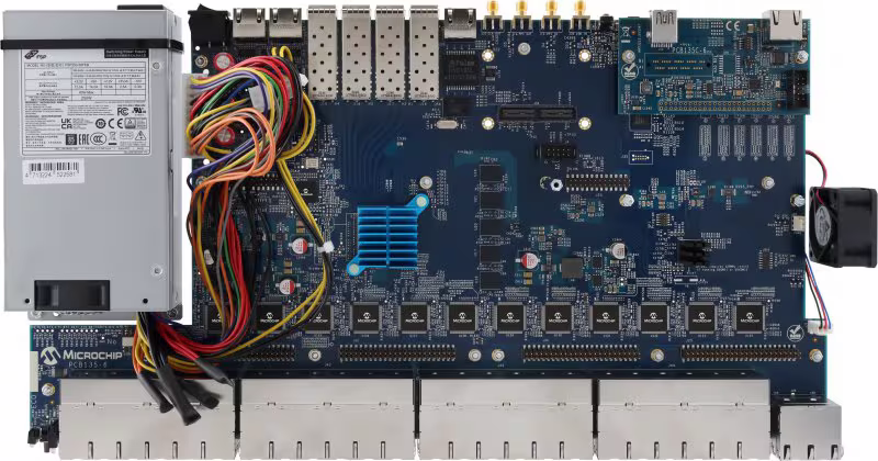
The board features:
-
1x VSC7558 switch (with Enterprise Ethernet features)
-
48x 1G (tri-speed) RJ45 front ports using 12x LAN8814 Quad PHYs, each con- nected to VSC7558 through QSGMII
-
4x 2.5G (quad-speed) RJ45 front ports using a single GPY241 Quad PHY. As default, each port connects to VSC7558 through 4x 2.5G SGMII. It is possible to use one single USXGMII.
-
4x SFP28 (25G) module slots on rear panel connected to VSC7558 through SFI high speed
-
One additional 1G (tri-speed) RJ45 Ethernet port using an on-board VSC8211 PHY, which is connected to VSC7558 NPI port through SGMII, when adding the loopback add-on PCB
-
On-board SyncE DPLL Redwood/ZL30772 (replaceable with the cheaper non-PTP ZL30256, if SyncE and PTP operation is not required) to generate the board required clocks
-
Additional support for a range of Microchip SyncE module designs through a SyncE feature connector (all clocks still go through the on-board DPLL)
-
Four SMAs connectors and two ITU-T G.8275-compliant RS-422 interfaces (1 PPS
ToD input and output) for SyncE and PTP applications -
Serial UART port (USB) for local management and software debugging by using a firmware-driven Command Line Interface (CLI)
-
The USB driver also provides connection to a power monitoring device for current monitoring of the 0.9V, 0.95V, 1.0V, and 1.1V power supplies.
-
-
Reset button at rear and user input button on front.
-
System status LED (bi-color green/red) and port status LED (bi-color green/yellow) per network port for link and activity indication
-
Standard 240/110 VAC 200W PSU
-
Option for PoE add-on, such as EV14Y36A (IEEE 802.3af/at/bt Type 4 standard compliant)
3. Board Name Overview
The name used in the device trees for the Linux Kernel is the board order number, as this has been created at a very early stage of the project.
To allow you to move between the different names that are in use, you can use the table found below:
| Internal Board Name | Board Order Number |
|---|---|
PCB134 |
VSC5640EV |
PCB135 |
VSC5641EV |