HSR/PRP
REDBOX |
Redundancy Box |
HSR |
High-availability Seamless Redundancy |
PRP |
Parallel Redundancy Protocol |
DANH |
Doubly Attached Node in HSR mode |
DANP |
Doubly Attached Node in PRP mode |
DAN |
Doubly Attached Node |
SAN |
Singly Attached Node |
LRE |
Link Redundancy Entity |
RCT |
Redundancy Control Trailer |
SMAC |
Source Media Access Control (address) |
HSR and PRP are two protocols used to implement zero-loss redundancy on wired Ethernet and are defined by International Electrotechnical Commission (IEC) in the 62439-3 standard, edition 4, 2021-12. Although similar, the two protocols uses different network topologies and tagging schemes (detailed in DANH and DANP).
HSR and PRP are implemented in hardware, using RedBoxes. A RedBox is a 3-port device designed to connect PRP, HSR, or single-threaded networks, but can also operate as a standalone DANH or DANP endnode. Every RedBox contains a node table of SMACs learned on LRE ports, and a duplicate discard table of SMAC and sequence number pairs, seen on the LRE ports.
1. Supported RedBox modes
The following modes of operation are supported:
-
DANH
-
DANP
-
HSR-SAN (requires iproute2 v6.10)
-
PRP-SAN
-
HSR-HSR
-
HSR-PRP
1.1. DANH
HSR is designed to function in a ring topology, ensuring zero recovery time. An HSR ring is composed of DANs each equipped with two ring ports, as depicted in the subsequent figure. These specific DANs are referred to as DANHs. A DANH simultaneously sends the same frame through both LRE ports, resulting in two frame copies circulating both clockwise and counter-clockwise in the ring. A unicast frame, whose final destination is a node within the ring, travels in both directions around the ring until it reaches the destination node. The destination node forwards the first error-free frame copy to its higher layers or, in the case of HSR-SAN, to the bridge-side after removing the HSR tag. A unicast frame, whose final destination is not a node within the ring, is forwarded by every node in the ring until it reaches the originating node, where it is dropped.
In DANH mode, the RedBox operates as a standalone DANH node, not forwarding any frames between the bridge side and the LRE side.
1.1.1. HSR tag
HSR frames are identified by their HSR tag, which consists of the following fields:
-
16-bit Ethertype (HSR_EtherType = 0x892F)
-
4-bit path identifier (PathId)
-
12-bit frame size (LSDUsize)
-
16-bit sequence number (SeqNr)
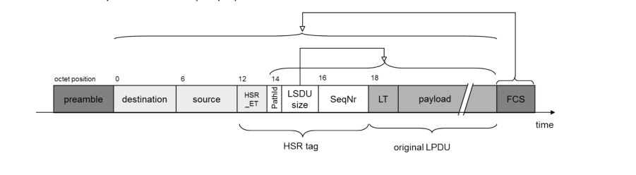
In case the frame contains a VLAN tag, the HSR tag is inserted after the VLAN tag.
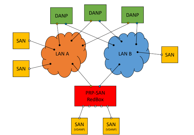
1.2. DANP
PRP is designed to offer fail-safe redundancy in Ethernet networks, ensuring immediate recovery of any failures. PRP introduces redundancy at the node level by connecting two network interfaces to two separate and disjoint parallel networks, LAN A and LAN B. These two ports are referred to as Link Redundancy Entity (LRE) ports. The LRE port connected to LAN A is known as Port A (or LREA), while the one connected to LAN B is termed Port B (or LREB). Nodes that are connected to both LAN A and LAN B are termed Doubly Attached Nodes (DANs), and within a PRP network, these DANs are referred to as DANPs. All DANPs and all RedBoxes in the network can communicate, and will still be able to communicate if one of their LRE ports goes down.
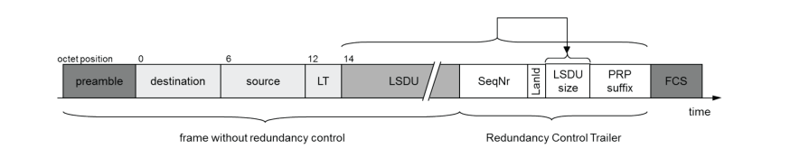
A DANP sends the same frame simultaneously through its two LRE ports towards the destination node. A PRP tag (Redundancy Control Trailer, RCT), containing a sequence number, is added to each frame copy to help the destination node distinguish between duplicate frames. The first error-free frame copy that arrives at the destination DANP node, gets the RCT removed and the destination DANP node sends the frame to its higher layers.
In DANP mode, the RedBox operates as a standalone DANP node, not forwarding any frames between the bridge side and the LRE side.
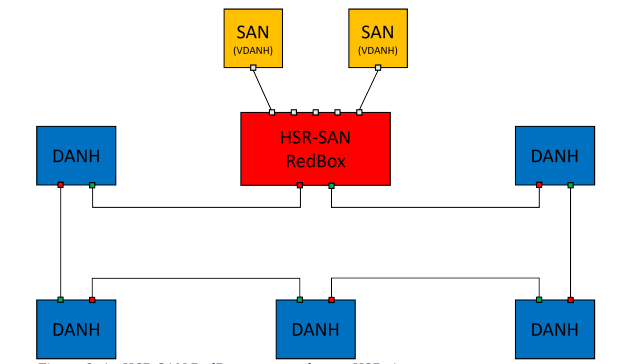
1.3. HSR-SAN
In HSR-SAN mode, the RedBox operates much like in DANH mode, except frames are also forwarded to/from the SAN, with tags pushed and popped. SANs are standard Ethernet devices with only one port. SANs cannot be directly attached to the HSR ring, since all devices within an HSR ring must be capable of processing HSR tags. Instead, it must be connected through a RedBox on the RedBox’s bridge-side. The RedBox is responsible for managing the pushing and popping of HSR tags on their behalf.
2. Node table
To manage properties of nodes on the LRE-side, a RedBox maintains a node table. The node table tracks SMACs seen in frames received on LRE ports. Among other things, it contains a field that indicates whether a node is a SAN or a DAN. Frames are forwarded in the RedBox, depending on the node type of the matching (if any) table entry. Table entries are aged out after a certain amount of time of inactivity from an SMAC, and if no supervision frames mentioning that SMAC have been received on an LRE port. Besides the SAN/DAN flag, an entry in the table contains per LRE-port counters, for the number of data frames it has received.
3. Discard table
To determine if a frame is subject to duplicate discard, a RedBox maintains a duplicate discard table, that keeps track of SMACs and sequence numbers. If a frame, with the same sequence number has already been received from a node, the duplicate is discarded. Table entries are aged after a certain amount of time of inactivity.
4. Supervision frames
Supervision frames are periodically transmitted to notify other DANs connected to the PRP network or HSR ring about their or a SANs presence. A supervision frame is a multicast frame transmitted to DMAC 01-15-4E-00-01-xx, where xx is configurable. The EtherType of a supervision frame is 0x88FB.
5. Configuration
5.1. DANH
# ip link add name hsr0 type hsr slave1 eth0 slave2 eth1
# ip link set hsr0 up
This creates a new interface 'hsr0' and configures a new RedBox for DANH mode, with eth0 as LREA and eth1 as LREB.
5.2. DANP
# ip link add name prp0 type hsr slave1 eth8 slave2 eth12 proto 1
# ip link set prp0 up
This creates a new interface 'prp0' and configures a new RedBox for DANP mode, with eth8 as LREA and eth12 as LREB.
5.3. HSR-SAN
# ip link add name hsr_san0 type hsr slave1 eth16 slave2 eth20 interlink eth21
# ip link set hsr_san0 up
This creates a new interface 'hsr_san0' and configures a new RedBox for HSR-SAN mode, with eth16 as LREA, eth20 as LREB and eth21 as LREC. The SAN is connected on the bridge side through LREC. Only one SAN can be connected on the bridge side.
5.4. Constraints
Both LRE ports must be attached to the same taxi bus in hardware. The following shows a mapping between front ports and taxi bus. First row contains the front ports attached to taxi bus 0. Second row contains front ports attached to taxi bus 1, and so on.
0 |
4 |
1 |
2 |
3 |
5 |
6 |
7 |
28 |
29 |
8 |
12 |
9 |
13 |
10 |
11 |
14 |
15 |
||
16 |
20 |
17 |
21 |
18 |
19 |
22 |
23 |
||
24 |
25 |
||||||||
26 |
27 |
6. Status
There is a number of debugfs entries, that can be queried to show RedBox configurations and node tables.
6.1. Node table
# echo <instance> >/sys/kernel/debug/sparx5/redbox_idx
# cat /sys/kernel/debug/sparx5/redbox_htable
                                   Rx                    Last Seen             Rx Wrong LAN
                                   --------------------- --------------------- ---------------------
Inst MAC Address       Node Type   Port A     Port B     Port A     Port B     Port A     Port B
---- ----------------- ----------- ---------- ---------- ---------- ---------- ---------- ----------
   0 a0:36:9f:67:c1:10 DAN                  5          0          2          7          0          0
   0 8e:df:cf:d7:e8:02 LOCAL                0          0          0          0          0          0
   0 8e:df:cf:d7:e8:01 LOCAL                0          0          0          0          0          0
Frames destined to an entry listed as LOCAL, are redirected to the CPU. Currently, the LREA and LREB ports are learned as LOCAL entries upon RedBox configuration. Rx is the number of frames received on the port. Rx Wrong LAN is the number of frames, where the lanid of the frame mismatches with the lanid of the LRE port it was received on. This is used to detect misconfigurations in the network. Last seen is a counter that is incremented each aging period. When the counter >7 the entry is aged and removed.
6.2. RedBox table
# cat /sys/kernel/debug/sparx5/redbox
Inst Oper. State Taxi Mode    Port A     Port B     Port C     Warnings
---- ----------- ---- ------- ---------- ---------- ---------- --------
   0 Active         0    DANH eth0       eth1       N/A        no
   1 Active         1    DANP eth8       eth12      N/A        no
   2 Active         2 HSR-SAN eth16      eth29      eth21      no
   3 Inactive
Currently, any Rx Wrong LAN count above zero, will cause a warning notification for the RedBox.