Restoring SecureBoot Images
In case of a blank eMMC or NOR device, the following instructions can be applied for the initial bringup of a LAN969x or LAN969x SoC.
| The procedure described here will not work for the EVB-LAN9668 (PCB8290), as this board is using a USB device as console and TFA monitor for lan966x it is using FlexCom3 which is a different device. For this board you will have to use a flash programmer. An alternative would be to wire cables to the board to get access to FlexCom3 to use the method described here. |
1. Reference information
This is where you can find more details about enabling EVB image restoration:
| SoC Name | Strapping Pins | Monitor Mode | USB Device |
|---|---|---|---|
LAN966x |
MCP2221 USB-I2C/UART Combo |
||
LAN969x |
MCP2200 USB Serial Port Emulator |
2. How to restore an image using FWU
2.1. Enable TF-A-Monitor on the default console
This section will give an overview on how the TF-A monitor can be loaded to the SoC and used for e.g. writing a FIP or a GPT image on a flash device.
The following description is based on a host PC running Ubuntu Linux:
-
Set the strapping mode on the eval board to the "Monitor Mode" to enabling the UART monitor mode. See previous section for the details.
-
Connect the eval board via USB cable to the host PC.
-
The host machine should now enumerate a new USB Device (use lsusb) and a TTY device like e.g. '/dev/ttyACM0'.
-
From now on, no other application should be attached to this port (e.g. Putty or Termhub).
-
Use a Chrome or MS Edge browser and open the fwu.html file in the address bar. This file can be found inside the artifacts archive.
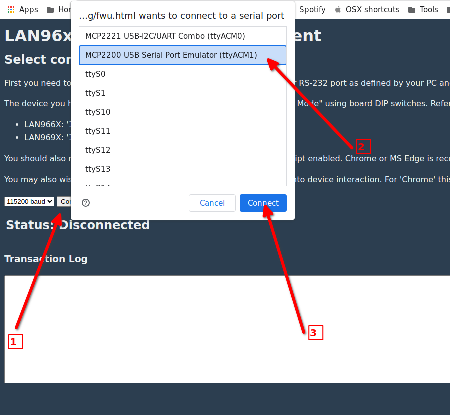
Please follow the instructions and the red arrows, illustrated on the previous screenshot.
-
Arrow #1, Press the [Connect Device] button
-
Arrow #2, Choose the appropriate console interface in the dropdown menu
-
Arrow #3, Press [Connect] button
-
After successful connection, the 'BL1 bootstrap' page should be loaded.
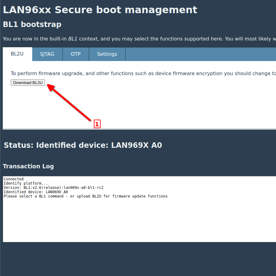
2.2. Download BL2U
This downloads and runs the BL2U image embedded in the fwu.html page.
This image will allow other firmware images to be updated and various other maintenance operations.
-
Arrow #1, Press the [Download BL2U] button
After download and execution, the 'BL2U bootstrap' screen should be appear.
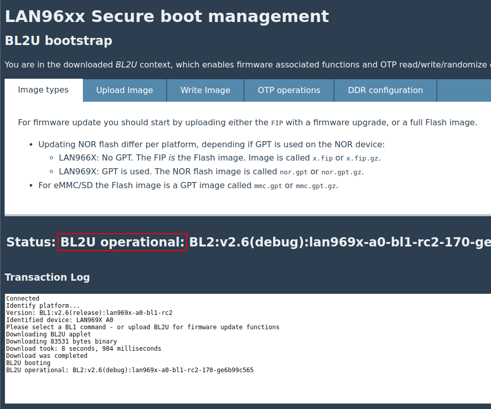
Notice the "BL2U operational" information.
2.3. Program NOR with FIP
The main purpose of this description is to a write a FIP file to a blank NOR device. Be aware, that only a FIP file format can be written to the NOR flash. Using a GPT file will not work here.
The following description assumes that the TF-A monitor mode has been started.
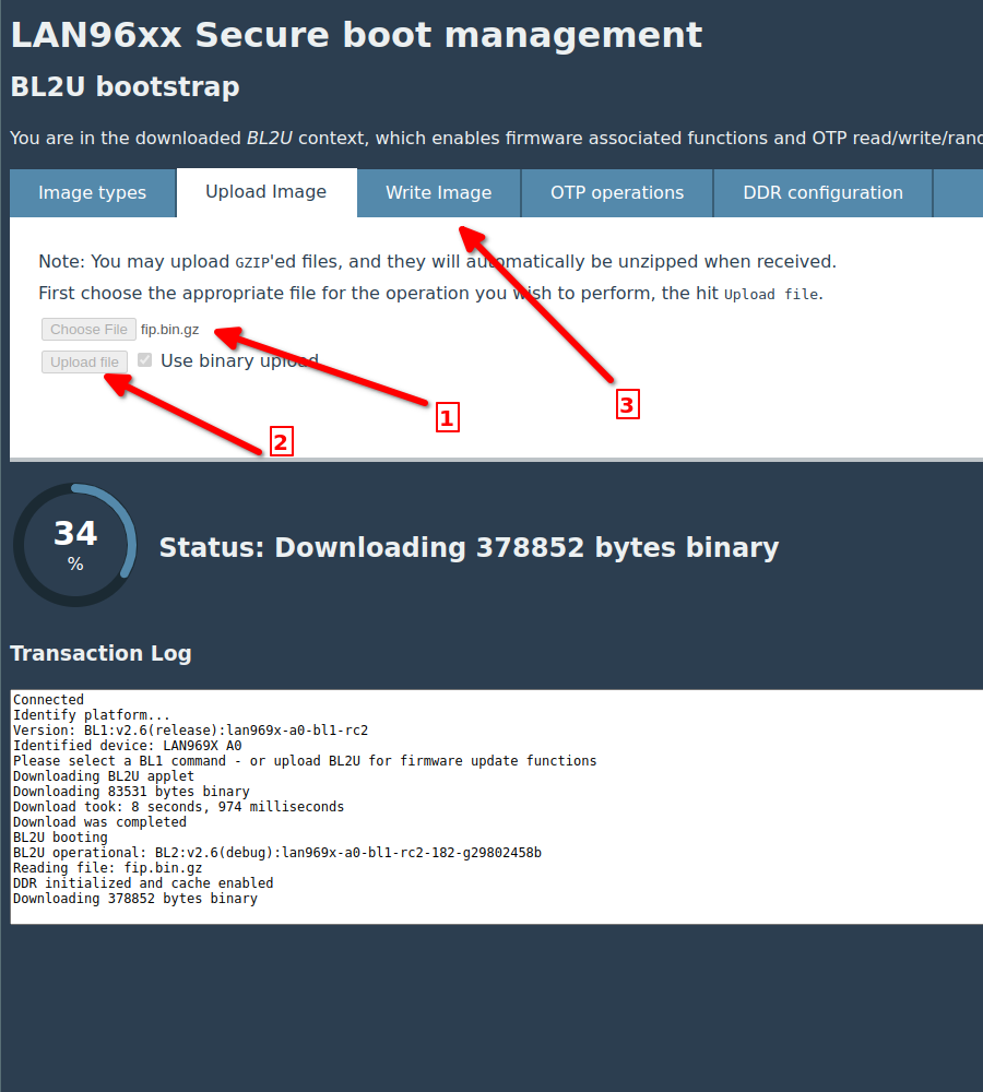
Please follow the instructions and the red arrows, shown on the previous screenshot.
-
Arrow #1, Choose the proper .fip file [Choose File].
-
Arrow #2, Upload the file by pressing the [Upload file] button.
-
Arrow #3, When the upload has finished, press the 'Write Image' tab
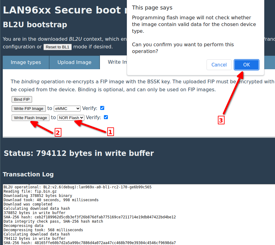
-
Arrow #1, Change dropdown value to [NOR Flash] device.
-
Arrow #2, Press the [Write Flash Image] button.
-
Arrow #3, Press the [OK] button to confirm the operation.
-
Wait until the write operation is completed. The process can take a few minutes. The progress can followed in the [Transaction Log:] field.
-
Change the strapping mode back to normal the NOR boot mode. See Reference Information
-
Reset the board
2.4. Program eMMC with GPT image
The main purpose of this description is to a write a GPT image to a blank eMMC device. Writing this image will trigger following actions to the device:
-
Creates a GPT based partition table and all required partitions.
-
Stores a FIP file inside the 'fip' named partition.
-
According the chosen GPT image, the BL33 can contain an 'UBoot' or a 'Linux' image as payload.
| A simple file copy of the GPT image to the eMMC device will not work! Only a raw byte copy will work correctly. |
The GPT image can be written to the eMMC device using following methods:
-
Using UBoot with network and upload/write the GPT image with mmc commands
-
Using external programmer and write the GPT image to the eMMC address offset of 0x0 (zero).
-
Use the HTML5 based firmware update browser tool (fwu.html).
This section will describe, how to proceed with the third approach here. Therefore no further programmer hardware is required.
First boot into the TF-A monitor using the correct strapping pin setting. See Reference Information
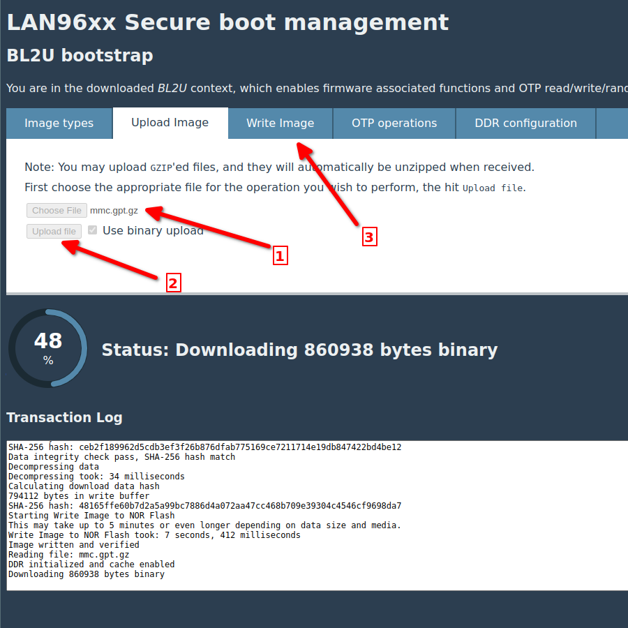
Then follow the instructions and the red arrows, illustrated on the previous screenshot.
-
Arrow #1, Choose now the proper .gpt file [Choose File]
-
Arrow #2, Upload the file by pressing the [Upload file] button
-
Arrow #3, When the upload has finished, press the 'Write Image' tab
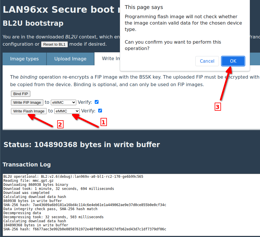
-
Arrow #1, Change dropdown value to [eMMC] device.
-
Arrow #2, Press the [Write Flash Image] button.
-
Arrow #3, Press the [OK] button to confirm the operation.
-
Wait till the write procedure has completed. This process can take a few minutes. The progress can followed in the [Transaction Log:] field.
-
Change the strapping mode back normal eMMC boot mode. See Reference Information
-
Reset the board
2.5. Program eMMC with FIP
A FIP file can only be programmed, if the eMMC device is already partitioned. If not please follow the description in the previous section.
This description is also valid for updating an existing FIP on the target.
The FIP file can be written by using one of this following methods.
-
Using UBoot console with network and upload/write the FIP using mmc commands
-
Use the HTML5 based firmware update browser tool (fwu.html).
We will focus here on the second approach.
First Boot into the TF-A monitor using the correct strapping pin setting. See Reference Information
Then follow the description for the BL2U bootstrap monitor page.
Please follow the instructions and the red arrows, shown in the previous screenshot.
-
Arrow #1, Choose the proper .fip file [Choose File].
-
Arrow #2, Upload the file by pressing the [Upload file] button.
-
Arrow #3, When the upload has finished, press the 'Write Image' tab
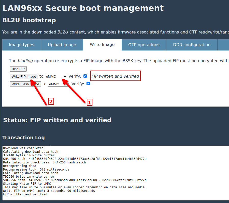
-
Arrow #1, Change dropdown value to [eMMC] device.
-
Arrow #2, Press the [Write FIP Image] button to start the operation.
-
Wait until the write operation has completed. The process can take a few minutes. The progress can followed in the [Transaction Log:] field.
-
Change the strapping mode back to normal the eMMC boot mode. See Reference Information
-
Reset the board