EVB-LAN9662 as a SPI Host
Introduction
This describes how to use one EVB-LAN9662 to control another EVB-LAN9662 using a SPI interface.
The method can be extended to control other Microchip Ethernet switch SoCs, but here we focus on the simple setup using two identical devices for demonstration purposes.
The SPI interface control is enabled in a LAN966x SoC when booting in strap mode 15.
In this mode the host has access to all registers in the CSR ring. These are the registers in the VML model that are not labelled with an instance name.
Examples:
| Name | Type | VML Link |
|---|---|---|
DEVCPU_GCB |
CSR |
https://microchip-ung.github.io/lan9662_reginfo/reginfo_LAN9662.html?select=devcpu_gcb |
PCIE_CFG |
amba_axi_top |
https://microchip-ung.github.io/lan9662_reginfo/reginfo_LAN9662.html?select=pcie_cfg |
In the examples above the SPI host can access the registers in DEVCPU_GCB directly but not the registers in PCIE_CFG.
Access to other register groups than CSR
In Microchip Ethernet Switches other register groups than the CSR group can be accessed indirectly via VCORE Access.
Host Configuration
To use the SPI connection from Linux userspace the Linux Kernel must provide a SPI character device that can send and receive data via a SPI controller in the host.
This requires that the Kernel configuration is changed and that a Device Tree node is added with a configuration for the SPI host controller and a sub node that has a SPI device.
This configuration is available for use with the current BSP release, but it must be enabled before it can be used.
This is done with a device tree overlay that adds the Flexcom2 SPI device to the default devicetree for the EVB. See LAN966x Overlays for more information.
To enable the SPI device the pcb variable in U-Boot must be set to:
pcb=lan9662_ung8291_0_at_lan966x#lan966x_pcb8291_fc2_spi_0_at_lan966x
to load both the main device tree and the overlay that provides the spi device configuration.
The source of the device tree overlay can be seen here: spidev2 overlay.
Client Configuration
The client EVB must be configured to boot into SPI device mode. This is done by setting the VCORE boot straps to 15. See Strapping PIN modes
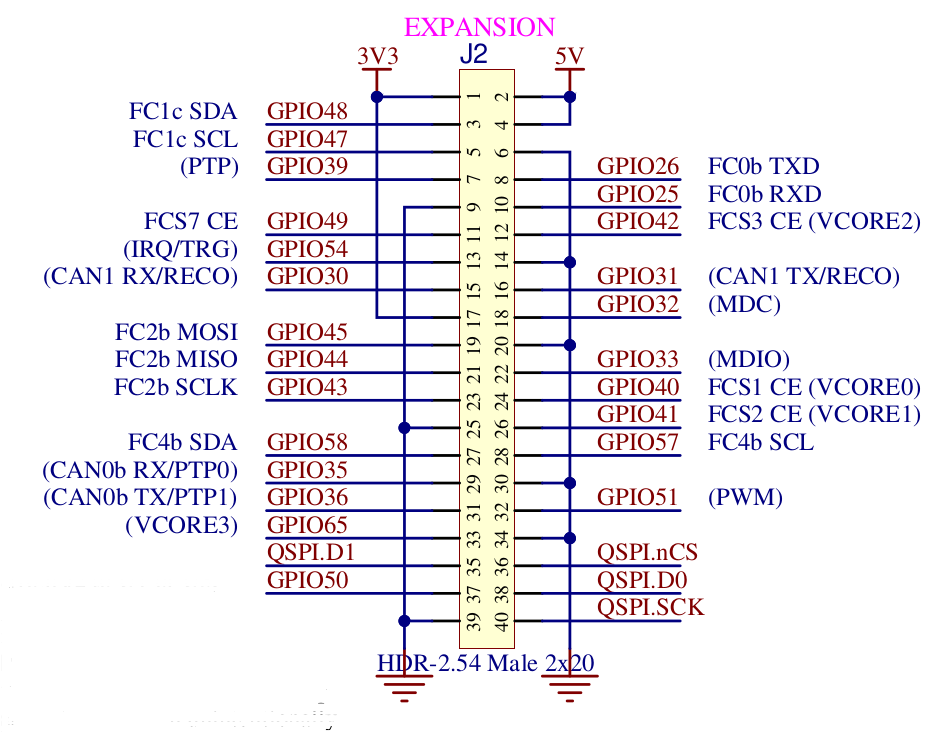
Connecting SPI devices
The two EVB-LAN9662 devices must be connected such that the host uses the Flexcom2 spi pins on its J2 extension connector and the client uses the QSPI device on its J2 extension connector.
Here is a wiring table:
| SPI Signal Name | EVB-LAN9662 Host | EVB-LAN9662 Client |
|---|---|---|
Chip Select |
J2_51 (GPIO51) |
J2_36 (SPI.nCS) |
Clock |
J2_43 (FC2b_SCLK) |
J2_40 (SPI.SCK) |
MOSI |
J2_45 (FC2b_MOSI) |
J2_35 (SPI.D1) |
MISO |
J2_44 (FC2b_MISO) |
J2_38 (SPI.D0) |
Ground |
J2_39 |
J2_39 |
And here is the pins on the J2 extension header:
SPI read and write format
The Microchip Switch SoC uses a simple read and write format for the SPI transactions.
The format uses a 3 byte payload
-
1 bit for read/write operation where 1 means write
-
23 bits for the address path
The address to be used is found in the VML model, but as VML uses words (32 bit) as the address unit you need to do a 2 bit shift when using this address and a mask to avoid changing the R/W bit.
For write operations this is followed by a 4 byte register value.
The endianness is always bigendian for the address part, but controlled by the if_ctrl endianness bit for the data part (the 32bit register value).
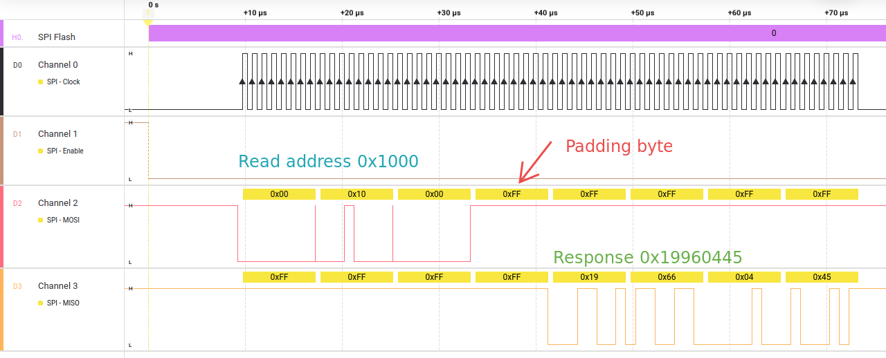
If the speed is sufficiently high you will need one padding byte for the read operation (above approx. 800KHz) between sending the address and sending 0xff bytes to receive the response.
Here is an example of reading the Chip ID:
Test tool use
The BSP root file system for the EVB-LAN966x includes a test tool that can read and write a register.
This tool is included only for demonstration purposes, but can be very useful when bringing up a SPI connection.
The tool is called spi-reg and this the help information:
    # spi_reg -h
    Usage: spi_reg spi_dev word_address_hex [new_value_hex]
    Options:
            -h | --help                     Show this help text
            -p | --padding BYTES            Use this number of padding bytes.  Default is 1
            -f | --frequency FREQ_HZ        Clock frequency to use in Hz.  Default is 1MHz

    Examples:
            Reading a value from word address 0x1000:
                    spi_reg /dev/spidev1.0 0x1000

            Writing 0xdeadbeef to word address 0x1002:
                    spi_reg /dev/spidev1.0 0x1002 0xdeadbeef
Now you need to find the name of your spi device:
    # ls -l /dev/spi*
    crw-------    1 root     root      153,   0 Jan  1 00:00 /dev/spidev2.0
Next read the work at work register address 0x1000:
    # spi_reg /dev/spidev2.0 0x1000
    DEV: /dev/spidev2.0, Freq: 1000000, Padding: 1
    RX: 00 10 00-19 66 04 45
Reading the 32-bit word at address 0x1000 returns the value 0x19660445.
The default settings: padding = 1 (one byte extra is sent to the device to allow it time to respond) and frequency = 1000000 is used to perform the operation. Normally you do not need to change the default values.
| The padding byte is not shown when the data is displayed in the console. |
Please note that the padding is only used when reading and must match the response time that the target device has otherwise the read result will not be correct.
Writing a value of 0x1234abcd to the address 0x1002 can be done like this:
    # spi_reg /dev/spidev2.0 0x1002 0x1234abcd
    DEV: /dev/spidev2.0, Freq: 1000000, Padding: 1
    Write value: 0x1234abcd
    TX: 80 10 02-12 34 ab cd -> OK
    RX: 00 10 02-12 34 ab cd
Here the tool reads back the updated value and compares it with the value provided on the command line.
Appendices
Appendix A: Device Tree Overlay
This is what the device tree for EVB-LAN9662 looks like when enable Flexcom2’s spi interface:
/dts-v1/;
/plugin/;

#include <atmel-flexcom.h>
#include <gpio.h>

/ {
	fragment@0 {
		target = <&flx2>;
		__overlay__ {
		    atmel,flexcom-mode = <ATMEL_FLEXCOM_MODE_SPI>;
		    status = "okay";

		    spi2: spi@400 {
			pinctrl-0 = <&fc2_spi_pins>;
			pinctrl-names = "default";
			cs-gpios = <&gpio 51 GPIO_ACTIVE_LOW>;
			status = "okay";

			spi@0 {
			    compatible = "spidev";
			    reg = <0>;
			    spi-max-frequency = <1000000>;
			};
		    };
		};
	};

	fragment@1 {
		target = <&gpio>;
		__overlay__ {
			fc2_spi_pins: fc2-spi-pins {
				/* SPI - SCLK, MISO, MOSI */
				pins = "GPIO_43", "GPIO_44", "GPIO_45";
				function = "fc2_b";
			};
		};
	};
};