SW Tailoring
The VelocityDRIVE-SP SW packets offered by Microchip support a given Switch-SoC along with some selected peripherals (like PHYs and flash chips). But to build a functional switch, the SoC needs to be mounted on a board, and when this board is designed, certain decisions are made. This includes:
-
Port map and configuration
-
What ports are used, what PHYs and what speeds
-
Physical port numbers vs serdes/rgmii numbering
-
etc.
-
-
GPIO mappings
-
Board reset, status LED, etc.
-
-
Factory default configuration
-
Example: if the box has a label saying the default IP is 10.0.0.1, then this configuration needs to go into the factory defaults.
-
As the SW is designed to support a SoC, not a board/box, some tailoring layer is needed where the decisions made when designing a given board (schematic) can be augmented into the generalized SoC SW.
This is referred to as SW-tailoring and is covered in detail in this part of the documentation. VelocityDRIVE-SP is distributed as binaries, and all the tailoring options described here can be used on the binary packets of VelocityDRIVE-SP. The mechanisms described here are the same as what Microchip uses to support their own EVBs, and the EVB tailoring is included in the binary packets as a reference example.
The board tailoring features can be boiled down to the following categories:
-
Board-config: also referred to as the Board-YANG because we use a YANG module to guard the schema on what can be put into the board-config.
-
This file includes all the information from the schematic of the boards, which the SW needs to know about to be able to adjust its behavior on a given board.
-
-
Factory defaults: This is the configuration applied if no user configuration has been saved on the board, or if a board is being reset to factory defaults.
-
The factory defaults are stored in the board-config file along with the other settings.
-
-
EXTMOD: This is specific functionality which optionally can be provided by the customer.
-
The extmod is stored in the board-config file along with the other settings.
-
-
Secure Boot: This is about signing the artifacts with keys controlled by the customer.
1. Build process overview
To understand how the SW Tailoring is working, it is a good idea to look at the build process, which show how artifacts are generated and what are the inputs, outputs and dependencies.
1.1. EXTMOD (optional)
extmod is a load-able C library capable of letting the customer implement
certain function to extend or tailor the behavioral of the binary SW packet.
extmod is an optional component and if not needed, it can be skipped entirely.
Build-wise, this is the first step as it has no dependencies. The input here is
the C sources, which are compiled and linked using the GCC tool-chain to
generate a ELF file. The ELF file is then processed by a script which take
care of extracting only the object-code, and extract information on what region
needs to be executable (the code) and what needs to to be RW (initialized data
and BSS)
These steps are illustrated below:
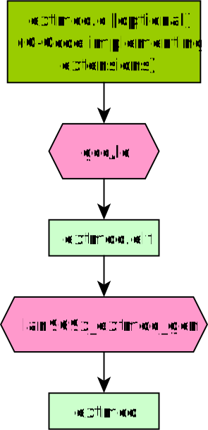
In the end a "extmod" file is generated, which contain the text and region information. This file will be used as input in the next step.
1.2. EXTMOD PHY Support (Optional)
extmod offers PHY support, enabling a third-party PHY driver to be built and added to the final binary (as described above). This PHY driver will be called by the application in the same manner as other onboard PHYs, following a defined call order:
-
lm_extmod_init(void);// Called before anything else -
lm_extmod_create();// Probes the extmod PHY -
lm_extmod_reset();// Soft resets the PHY -
lm_extmod_conf_set();// Sets up mode-specific parameters -
lm_extmod_poll();// Called periodically for status information
If a function isn’t needed for the target PHY, it can be left empty.
More information is available in this header file: lm_extmod.h
To enable this feature, an extmod flag must be added to the PHY configuration in the board YAML file. See file: lan9696TSN-ev23x71a-extmod.yaml
The application also supports callout functions that the PHY can use, such as MIIM support, which are described in header file: lm_extmod_callout.h
A complete example of how to implement such a PHY (1G Clause-22) is provided in source file: extmod_sample.c
1.3. Board configuration
The board configuration, a CBOR encoded data structure including all the
tailoring configuration, data and code. The docs/sw_refs/yang/board.yang file
in the binary packet, provide the YANG schema documenting the individual fields.
The board configuration contains the following major sections:
-
board:drivers-
This list all the driver which needs to be instantiated at boot, and provide the needed parameters. This section conceptually similar to device trees.
-
-
board:capabilities-
This is used to enable/disable certain features, and to control the scale and resource consumption for a given resource.
-
-
board:factory_default_config-
This is the configuration to apply when the board is reset to factory defaults.
-
-
board:extmod-
This is the loadable C library from previous section.
-
When creating the board CBOR file the following input is needed:
-
A YAML file containing the
board:drivers,board:capabilitiesandboard:factory_default_config. -
Optionally the
extmodfile from previous section. -
The YANG catalog with all the SID files. This is needed to convert all the string based identifier to ID. This YANG catalog is part of the binary packet.
The bc2cbor will take these inputs, and generate the board.cbor file.
This process is illustrated below:
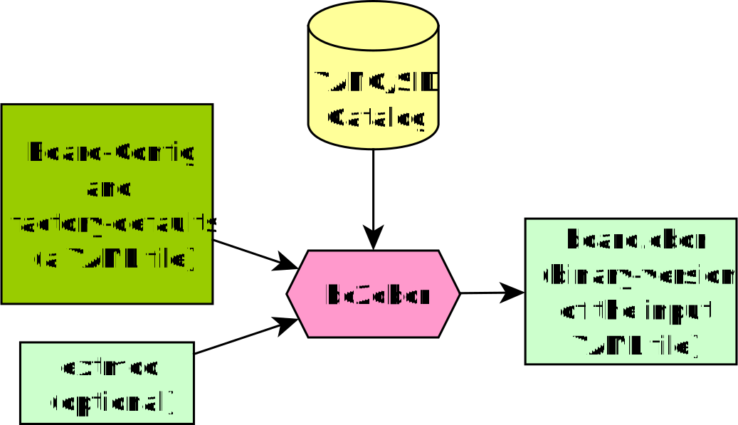
The resulting output is then used as input in the next step.
1.4. Image generation
The final step is the image generation. Here the board.cbor form the earlier
step is appended to the binary, then it is signed for secure boot, and wrapped
into a FIP image.
This process is illustrated below:
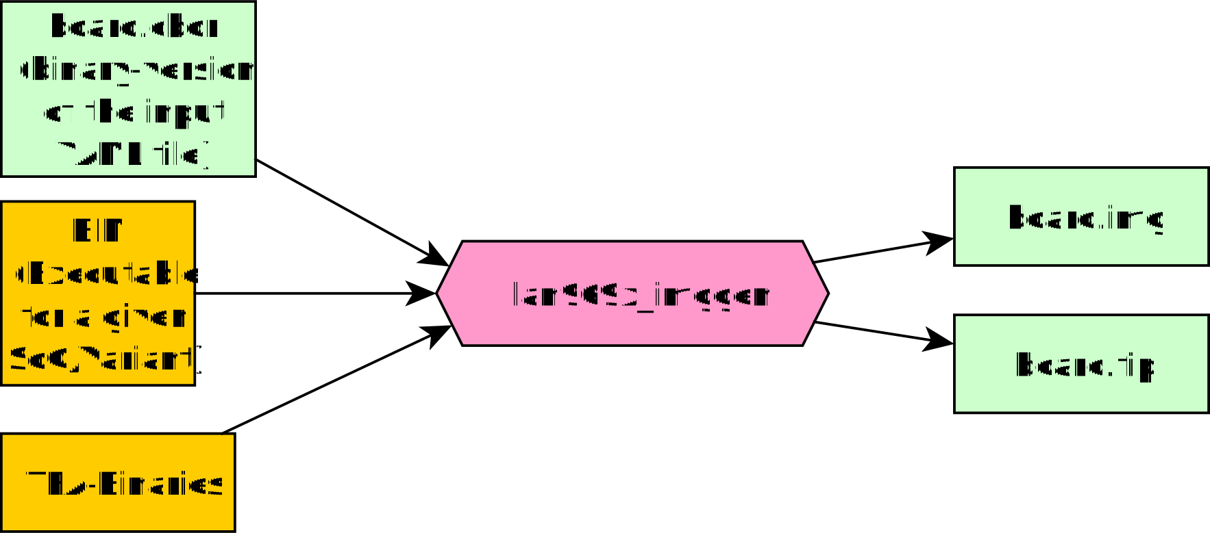
Beside form producing a FIP, an img file is also produced. The img file
contains both the bootloader and the FIP provisioned in both FW partitions. This
img file can be programmed directly into the flash.
The resulting image is now ready for use.
2. Bootloader flash tailoring (LAN969x)
The board-config flash_static container covers how VelocityDRIVE-SP talks
to the SPI-NOR flash. The bootloader is a separate stage with its own settings: BL2
runs before the application, and learns the flash clock and bus width from its
own device tree, fw_config, which is embedded in the secure FIP.
This matters when a board cannot sustain the default flash timing. Lowering only the application’s settings leaves BL2 still driving the flash at its original clock and width during boot, which is exactly when a marginal board is most likely to fail. A board that needs slower or narrower flash generally needs both stages lowered.
The device-tree source is delivered as target/lan969x/tfa/fw_config.dts, and
the three relevant properties are marked TAILOR in it:
| Property | Meaning |
|---|---|
|
The clock feeding the QSPI controller, in Hz. |
|
BL2’s clock ceiling for the flash, in Hz. |
|
|
The defaults are 100 MHz and quad. Useful frequency values: 0x5f5e100 =
100 MHz, 0x2faf080 = 50 MHz, 0x17d7840 = 25 MHz.
To tailor it, copy the file, edit it, and point the build at your copy:
cp target/lan969x/tfa/fw_config.dts my_fw_config.dts
# edit the TAILOR properties in my_fw_config.dts
cmake --preset lan969x -DLAN969X_FW_CONFIG_DTS=$PWD/my_fw_config.dts
cmake --build --preset lan969x
The build compiles the source with dtc and embeds the result in the secure
FIP. No separate signing step is needed: the certificate chain is re-signed on
every build, so the new device tree is measured into it automatically.
To confirm what a built image actually carries, unpack it:
fiptool unpack --force --fw-config /tmp/fw_config.bin \
    build-lan969x/target/lan969x/lan969x_EV23X71A-secure.fip
dtc -I dtb -O dts /tmp/fw_config.bin | grep -E 'spi-max-frequency|bus-width'
2.1. Bringing up a board with marginal flash
A flash setting the board cannot sustain corrupts data rather than failing cleanly, and corrupted reads can present as almost any other fault. Change one thing at a time:
-
Build with both stages at their most conservative —
single_1_1_1/ 25 MHz in the board config, and 25 MHz single-line infw_config.dts. -
Confirm the board boots, survives a firmware update, and can save and restore its configuration. This exercises the full flash write and read path.
-
Raise one stage by one step, rebuild, and repeat. The application reports the clock it settled on at boot —
QSPI0 running at N Mhz— so you can confirm each step took effect before moving on. The read protocol is not logged; a wrong one corrupts reads rather than announcing itself, which is why the read-back check in the previous step matters. -
Stop at the last setting that is stable with margin, not at the first that appears to work.
Do not try to confirm a change by measuring throughput from a host. Every path to the device is a serial transport of a few KB/s, which is orders of magnitude slower than the flash at any of these settings, so the figure is dominated by the link and does not move when the flash speed does.
The boot report is the signal instead. It is printed before any host tooling attaches, and the application emits nothing unsolicited afterwards, so capture it across a restart rather than sampling once the device is up.